From Controller to LED Display Solutions: How Data Cables Carry Signals?
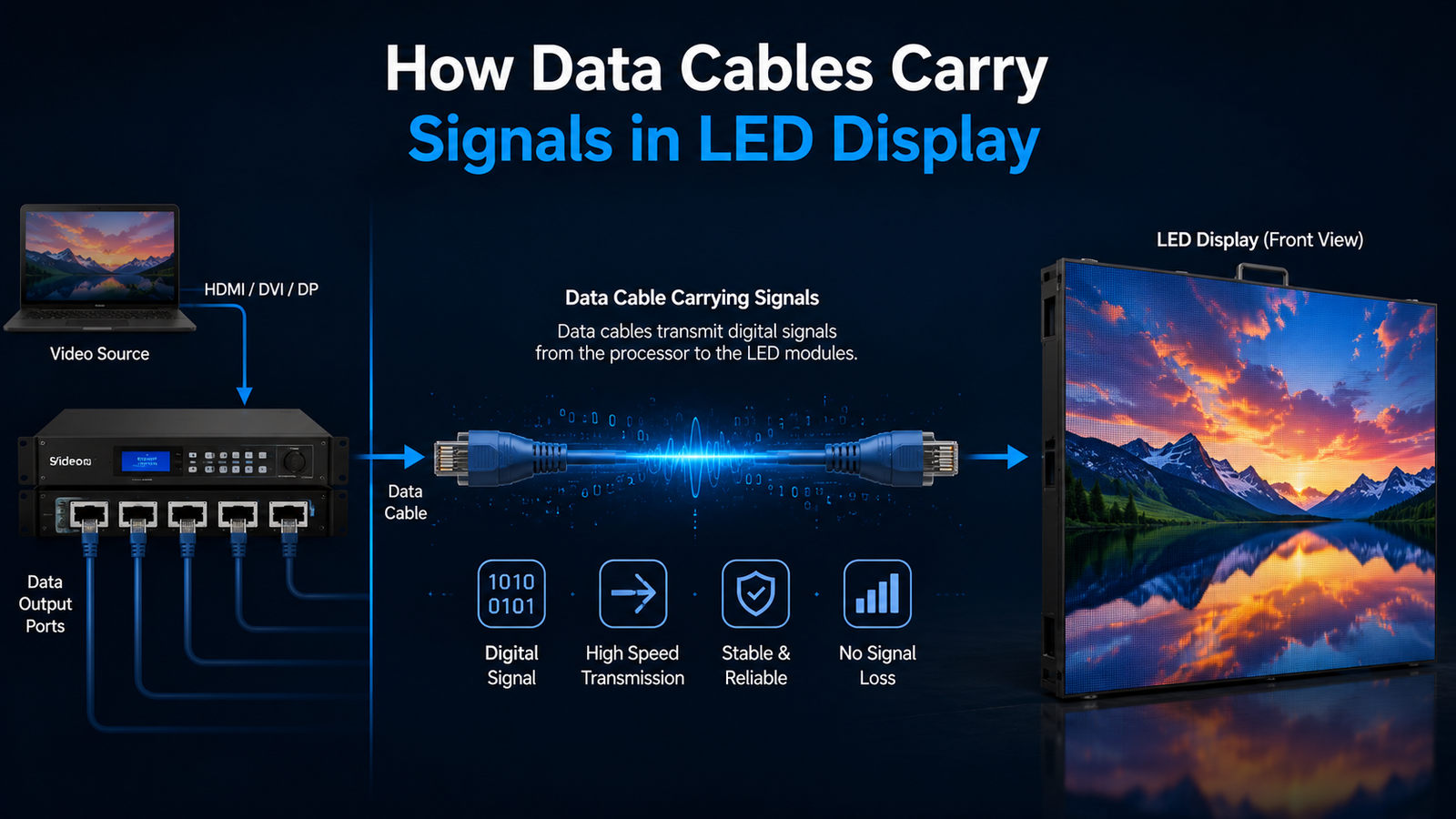
An LED screen may look like a single, seamless surface from the front, but behind that visual experience is a carefully connected signal chain. Content starts from a media player, computer, camera, or other source, reaches a controller, travels through data cables, passes across receiving cards, and finally reaches individual LED modules. Every stage plays an important role in ensuring that the intended image appears correctly on the screen.
This signal journey becomes especially important when designing reliable LED Display Solutions for corporate offices, retail spaces, control rooms, auditoriums, stadiums, and public environments. A display can have excellent modules and high resolution, but poor signal distribution can still result in flickering, missing sections, image distortion, or complete signal loss.
Understanding how data cables carry display signals helps businesses, system integrators, and facility teams make better decisions about installation, troubleshooting, scalability, and maintenance. It also explains why cabling should never be treated as a minor installation detail.
In this guide, we will follow the signal from the controller to the LED screen and explain the role of data cables at every stage.
What Are Data Cables in an LED Display System?
Data cables are communication pathways that transfer digital display information between different components of an LED system. Unlike power cables, which deliver electrical energy, data cables carry information that tells the display what image, colour, brightness, and position each LED should produce.
In typical LED Display Solutions, the controller receives content from a source device and distributes the processed signal to receiving cards installed within LED cabinets. These receiving cards then communicate with LED modules so that the correct pixels illuminate at the correct time.
Depending on the system architecture, different interfaces and cable types may be used. Ethernet-based data connections are common in many modern LED installations, while other interfaces can be used between controllers, sending cards, receiving cards, and display modules.
The important point is simple: power makes the screen operate, but data tells the screen what to show.
How Does the Signal Travel From Controller to LED Screen?
The complete signal path can be understood as a series of connected stages:
Content Source → Video Processor/Controller → Sending Card → Data Cable → Receiving Card → LED Module → Visible Image
Each stage has a specific responsibility.
The content source may be a laptop, media server, camera, digital signage player, or another video device. The controller or video processor receives this input and prepares it according to the resolution and configuration of the LED wall.
The sending section then distributes the processed information through data connections. Data cables carry these packets toward receiving cards positioned behind the LED cabinets.
Receiving cards interpret the incoming information and distribute it to the LED modules. The modules contain the electronic components required to control individual pixels and Audio Visual integration.
When all these components communicate correctly, the viewer sees one continuous image.
This architecture is fundamental to dependable LED Display Solutions, particularly when a display contains hundreds or thousands of modules.
1. Content Source: Where the Signal Begins
Every LED display signal begins somewhere.
A laptop may send a presentation. A media player may send advertising content. A camera may provide a live video feed. A control room may send multiple dashboards simultaneously.
The source outputs a digital signal through an appropriate interface. Depending on the equipment, this may involve HDMI, DisplayPort, SDI, or another professional video interface and LED Display Solutions
At this point, the signal contains the visual information that eventually needs to appear on the LED screen.
However, the raw source signal is not always ready to control an LED wall directly. The display may have a different resolution, aspect ratio, cabinet arrangement, or pixel configuration.
That is where the controller becomes essential.
2. Controller: The Brain of the Signal Chain
The controller or video processor acts as the bridge between the content source and the LED display.
Its job is to receive the incoming video signal, process it, scale it when necessary, and distribute the output according to the LED wall’s configuration.
For example, a laptop may output a standard video resolution while the LED wall has a completely different native pixel arrangement. The controller maps the incoming content onto the display so that the image appears correctly across multiple cabinets.
Advanced LED Display Solutions may also require features such as:
- Input switching
- Scaling
- Multi-source management
- Image cropping
- Picture-in-picture
- Resolution management
- Brightness and colour control
- Redundancy
- Multiple output management
A correctly configured controller ensures that the data reaching the receiving cards corresponds with the physical structure of the LED wall.
3. Sending Card: Preparing the Data for Distribution
The sending card is responsible for transmitting processed display information toward the receiving cards.
In many installations, the controller and sending card may be integrated into the same processing architecture. In other configurations, they can function as separate components.
The sending section determines how much display information can be transmitted and how the output is divided among different data ports.
This becomes particularly important as the LED wall grows in size.
A small display may require only a few data connections, while a large video wall can require numerous outputs and carefully planned signal paths. Proper mapping prevents one data connection from becoming overloaded.
For large-scale LED Display Solutions, signal distribution should therefore be planned during the design stage rather than improvised after installation.
4. Data Cables: The Communication Highway
Now we reach the component highlighted in this article: the data cable.
The data cable carries the processed display information from the sending side toward receiving cards. In many LED systems, Ethernet-type cables are commonly used because they support high-speed digital communication and practical installation over structured routes.
But simply connecting a cable does not guarantee reliable performance.
Cable quality, length, routing, connectors, shielding, termination, and environmental conditions can all affect signal reliability.
A properly installed cable should provide stable communication without introducing unnecessary interference or connection failures.
In professional LED Display Solutions, cable management is therefore part of system engineering. Installers need to consider where cables will run, how they will be secured, how they will be labelled, and how technicians will access them during maintenance.
A cable that works during installation but becomes loose after months of vibration or maintenance activity can create avoidable display problems.
5. Receiving Card: Converting Data Into Display Instructions
The receiving card is positioned on the LED cabinet side of the system.
It receives the digital information transmitted through the data cable and distributes the relevant information to connected LED modules.
Think of it as a translator between the networked signal and the display hardware and LED Display Solutions.
A receiving card knows which part of the image belongs to its connected modules. It processes the incoming information according to the configured cabinet layout and sends the required instructions to the LED modules.
If the receiving card configuration is incorrect, the screen may show:
- Incorrect image positioning
- Repeated content
- Missing sections
- Flickering
- Colour abnormalities
- Misaligned cabinets
- Blank areas
This is why configuration is just as important as physical connectivity when commissioning LED Display Solutions.
6. LED Modules: Where Data Becomes Light
After the receiving card processes the signal, instructions reach the LED modules.
Each module contains multiple LEDs arranged into pixels. Depending on the technology and pixel pitch, these modules can provide different levels of resolution, brightness, colour accuracy, and viewing performance.
The data tells the module which pixels should illuminate and at what intensity.
For example, if the source sends a red graphic, the receiving system distributes the corresponding pixel information until the correct LEDs produce the intended red areas on the screen.
Thousands or even millions of individual pixels can therefore work together to create one continuous image.
This coordinated operation is what makes modern LED Display Solutions capable of producing detailed videos, graphics, presentations, advertisements, dashboards, and live feeds on large-format screens.
Data Cable Layout: Why Signal Mapping Matters?
A large LED wall is not simply one giant electronic panel. It consists of multiple cabinets, modules, receiving cards, and signal paths.
The data connection between these components must follow a logical structure.
Depending on the system design, cabinets may be connected in a daisy-chain arrangement, while multiple output ports from the sending system feed different groups of cabinets.
Signal mapping tells the controller which receiving card corresponds to which physical section of the screen.
For example:
Output 1 → Cabinet Row 1
Output 2 → Cabinet Row 2
Output 3 → Cabinet Row 3
The exact configuration varies according to the system, but the principle remains the same: the software configuration must match the physical cabling.
This becomes especially important when installing large LED Display Solutions with unusual aspect ratios, curved structures, creative shapes, or multiple display surfaces.
What Happens When a Data Cable Fails?
One of the most useful advantages of understanding signal flow is easier troubleshooting.
If a data cable becomes disconnected or damaged, the affected portion of the LED wall may stop receiving information. Depending on the architecture, this could affect one cabinet, a section of cabinets, or a larger part of the display.
Common symptoms include:
1. Blank Cabinet
A cabinet may stop displaying content because its receiving card is no longer receiving the expected data.
2. Flickering Image
An unstable connection can cause intermittent communication and visible flickering.
3. Missing Section
If a signal chain stops at a particular point, downstream cabinets may also lose the display signal.
4. Incorrect Image
A configuration or mapping issue can cause content to appear in the wrong location.
5. Random Visual Artifacts
Signal integrity problems may sometimes appear as unexpected pixels, lines, or distorted areas.
Troubleshooting should therefore start by identifying where the signal stops instead of immediately replacing LED modules.
Data Cables vs Power Cables:
A common mistake during LED installation is treating data and power cabling as interchangeable parts of the same system.
They perform completely different functions.
| Data Cable | Power Cable |
|---|---|
| Carries digital display information | Carries electrical power |
| Connects signal-processing components | Supplies electricity to display hardware |
| Determines communication between components | Enables components to operate |
| Signal quality affects image transmission | Power quality affects system stability |
| Usually connected to receiving cards | Connected to power supplies and distribution |
A display needs both systems to function correctly.
If power is available but data is missing, the screen may remain powered but display incorrectly or show no content. If data is available but power is absent, the relevant modules cannot illuminate.
This distinction is essential when designing reliable LED Display Solutions.
Indoor and Outdoor Applications:
Data transmission principles remain broadly similar across indoor and outdoor LED displays, but the installation environment changes the requirements.
For an Outdoor LED Display in Delhi, installers must account for environmental exposure, longer cable routes, cabinet protection, temperature variations, dust, moisture, and physical accessibility.
Outdoor systems are typically designed for higher brightness and greater environmental durability, especially where the screen must remain visible in daylight.
For indoor environments, an Indoor LED Video Wall may require finer pixel pitch and closer attention to visual uniformity because viewers are generally positioned nearer to the screen. Lightomated’s Vivid Series, for example, offers fine-pitch configurations, high refresh rates, and front-service options for indoor applications.
Whether the project is indoor or outdoor, structured signal distribution remains a fundamental part of dependable LED Display Solutions.
How to Ensure Reliable Data Transmission?
Several practical steps can improve signal reliability.
Use Appropriate Cable Quality
Choose cables suitable for the required transmission distance and installation environment. Avoid using damaged, poorly terminated, or unnecessarily long cables.
Keep Signal Paths Organised
Cable routing should be planned before installation. Clearly labelled connections make future maintenance much easier.
Avoid Unnecessary Cable Length
Longer routes can complicate installation and troubleshooting. Signal distribution should be designed around the actual cabinet arrangement.
Secure Connections Properly
Loose connectors can create intermittent failures that are difficult to diagnose. Every connection should be properly seated and secured.
Separate Signal and Power Routing Where Appropriate
Good installation practice helps reduce potential interference and keeps maintenance organised.
Maintain Proper Documentation
A cable map showing controller outputs, receiving cards, cabinets, and signal paths can save significant troubleshooting time.
These practices help LED Display Solutions deliver stable performance over extended operating periods.
Why Signal Design Matters for Large LED Displays?
As LED walls become larger, signal planning becomes increasingly important.
A small display might be relatively straightforward to troubleshoot because there are fewer cabinets and connections. A large command centre, stadium display, retail video wall, or corporate installation can contain hundreds of interconnected components.
In such environments, a single poorly documented connection can consume hours of troubleshooting time.
Proper signal architecture provides:
- Better system reliability
- Easier troubleshooting
- Cleaner installation
- Faster maintenance
- Better scalability
- Reduced downtime
- More predictable performance
This is particularly valuable for businesses investing in LED Display Solutions as long-term communication infrastructure rather than simply purchasing a large screen.
Choosing LED Display Solutions for Delhi NCR Projects
Environmental conditions, viewing distance, screen size, content type, and installation location should all influence the design of an LED project.
Businesses looking for an LED Display in Delhi NCR can evaluate indoor and outdoor configurations according to their specific application. Corporate offices may prioritise fine pixel pitch and close-viewing clarity, while retail and outdoor advertising environments may require different brightness and durability characteristics.
For control rooms, the display must support clear dashboards, live feeds, and continuous operation. For retail, visual impact and content flexibility may be more important. For auditoriums, viewing distance and image detail become key considerations.
The right design therefore starts with the application, not simply the screen size.
As LED technology continues to evolve, display systems are becoming larger, more flexible, and more integrated with other technologies.
Modern installations can combine LED walls with content management platforms, cameras, control systems, AV infrastructure, and network-based workflows.
How Lightomated Helps With LED Display Solutions?
Lightomated focuses on designing LED video wall systems around the requirements of the installation rather than treating every project as a standard screen deployment. Its solutions cover indoor and outdoor applications, with options designed for corporate spaces, retail environments, control rooms, auditoriums, and other large-format visual applications.
The company also highlights installation and maintenance support, including site inspection, structural planning, panel mounting, controller configuration, and calibration.
For organisations evaluating LED Display Solutions, this application-focused approach can help ensure that the display hardware, signal architecture, viewing conditions, and installation requirements work together as one complete system.
From the outside, an LED wall appears to be one seamless digital surface. Behind that surface, however, is a carefully engineered communication chain.
The journey begins with a content source, moves through the controller and sending system, travels through data cables, reaches receiving cards, and finally reaches individual LED modules. Every connection contributes to the final image.
That is why data cabling should never be considered an afterthought. Cable quality, signal mapping, routing, configuration, and maintenance all influence the reliability of the complete display system.
Whether you are planning an indoor corporate video wall, an outdoor advertising screen, or a large control-room installation, understanding the signal path makes it easier to select, install, maintain, and troubleshoot LED Display Solutions.
Ultimately, a great LED display is not created by the panels alone. It is created by making every part of the system from controller to cable to pixel work together seamlessly.